-
×
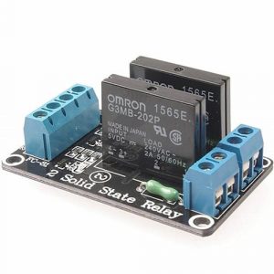 2 channel 5v Solid State Relay SSR Module 240V 2A Output with Resistive Fuse
1 × ₹290.00
2 channel 5v Solid State Relay SSR Module 240V 2A Output with Resistive Fuse
1 × ₹290.00 -
×
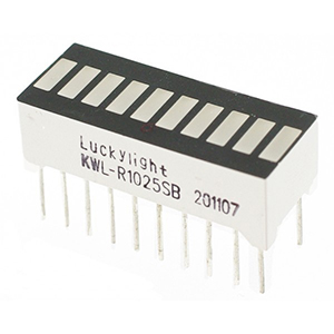 10 Segments LED Array Bar Graph Green Color
1 × ₹25.00
10 Segments LED Array Bar Graph Green Color
1 × ₹25.00 -
×
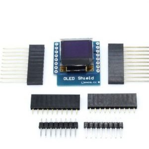 0.66 inc Mini I2C IIC OLED Display Module SSD1306 Shield
1 × ₹325.00
0.66 inc Mini I2C IIC OLED Display Module SSD1306 Shield
1 × ₹325.00 -
×
 5pcs PCB Mount SPDT Toggle Switch 2 Positions Slide Switch
1 × ₹20.00
5pcs PCB Mount SPDT Toggle Switch 2 Positions Slide Switch
1 × ₹20.00 -
×
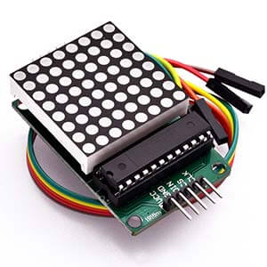 8×8 Dot LED Matrix Display LED Display Module
1 × ₹185.00
8×8 Dot LED Matrix Display LED Display Module
1 × ₹185.00 -
×
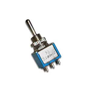 Panel Mount 3 Pins SPDT Toggle Switch – 3A 250V
1 × ₹29.00
Panel Mount 3 Pins SPDT Toggle Switch – 3A 250V
1 × ₹29.00 -
×
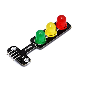 LED Traffic Light Signal Module 8mm LED
1 × ₹99.00
LED Traffic Light Signal Module 8mm LED
1 × ₹99.00 -
×
 74257 IC Quad 2 Input Multiplexer with 3 State Output 2 to 1 Multiplexer
1 × ₹33.00
74257 IC Quad 2 Input Multiplexer with 3 State Output 2 to 1 Multiplexer
1 × ₹33.00 -
×
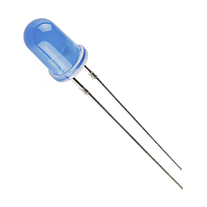 5mm LED – Blue (Pack of 50)
1 × ₹59.00
5mm LED – Blue (Pack of 50)
1 × ₹59.00 -
×
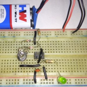 PWM LED Dimmer Kit Using 555 Timer IC
1 × ₹99.00
PWM LED Dimmer Kit Using 555 Timer IC
1 × ₹99.00 -
×
74163 IC Presettable Synchronous 4-Bit Binary Counter IC
1 × ₹85.00
-
×
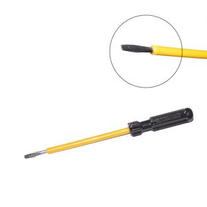 Electrician Pattern Insulated Screwdriver – 3.25mm x 100mm
1 × ₹25.00
Electrician Pattern Insulated Screwdriver – 3.25mm x 100mm
1 × ₹25.00 -
×
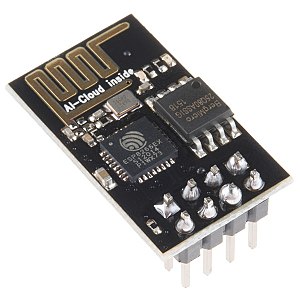
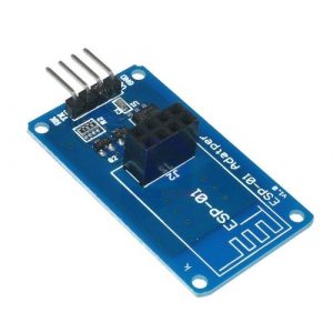 ESP-01 ESP8266 Adapter Programmer for Arduino
1 × ₹145.00
ESP-01 ESP8266 Adapter Programmer for Arduino
1 × ₹145.00 -
×
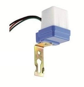 Light Photocell LDR Sensor Switch 220v
1 × ₹200.00
Light Photocell LDR Sensor Switch 220v
1 × ₹200.00 -
×
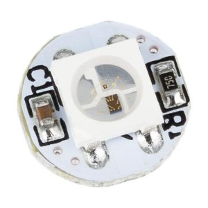 WS2812B Programmable/Addressable RGB LED Module
1 × ₹35.00
WS2812B Programmable/Addressable RGB LED Module
1 × ₹35.00 -
×
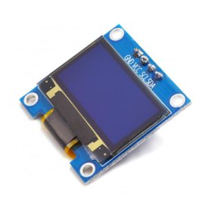 1.3 inch I2C IIC 128×64 OLED Display Module
1 × ₹589.00
1.3 inch I2C IIC 128×64 OLED Display Module
1 × ₹589.00 -
×
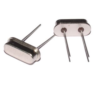 12 Mhz Crystal Oscillator | Quartz Crystal
1 × ₹10.00
12 Mhz Crystal Oscillator | Quartz Crystal
1 × ₹10.00
Subtotal: ₹2,253.00

There are no reviews yet.